
Max Hemken

A stunning view of a vibrant blue glacier set against snow-capped mountains, showcasing winter's beauty.

Choosing the right refrigerant

Selecting the right refrigerant is one of the most important decisions when planning, modernizing, or maintaining refrigeration and air conditioning systems. Besides technical performance, environmental aspects, legal requirements, and long-term cost-effectiveness play a crucial role today.

This article explains which criteria are crucial when selecting a refrigerant and what you should pay attention to in practice.


1. Environmental aspects: Keep GWP and ODP in mind

Modern refrigerants must not only be efficient, but also environmentally friendly.

Key figures:

  • GWP (Global Warming Potential): Indicates how much a refrigerant contributes to the greenhouse effect.

  • ODP (Ozone Depletion Potential): Describes the ozone depletion potential – usually 0 for modern refrigerants.

The F-Gas Regulation is increasingly restricting or banning refrigerants with a high GWP. Therefore, natural refrigerants such as CO₂ (R744), propane (R290) or ammonia (R717) , as well as modern HFO refrigerants, are becoming increasingly important.


2. Safety: Flammability and toxicity

Refrigerants are classified into safety classes (e.g., A1, A2L, A3, B2). These provide information about:

  • Flammability

  • toxicity

  • Handling requirements

While conventional HFC refrigerants were mostly non-flammable (A1), many more environmentally friendly alternatives are slightly or highly flammable (A2L or A3). This means that
the system technology, installation conditions, and safety measures must be adapted accordingly.

Professional planning is essential here.


3. Energy efficiency and performance

A good refrigerant is characterized by:

  • High volumetric cooling capacity

  • Good thermodynamic properties

  • Low compression end temperatures

  • Good efficiency in partial load operation

Efficiency directly impacts operating costs. A slightly higher purchase price can quickly pay for itself through lower energy consumption.


4. Future-proofing and availability

A crucial point is the long-term perspective:

  • Will this refrigerant be affected by future bans?

  • How stable is the price trend?

  • Are there sufficient spare parts and service expertise available?

Many operators are now consciously opting for future-proof solutions with a low GWP in order to avoid later retrofitting.


5. Typical areas of application

Depending on the application, different refrigerants are suitable:

Commercial refrigeration:
CO₂ (R744), R290

Industrial refrigeration:
Ammonia (R717), CO₂ cascade systems

Air conditioning systems:
R32, R290, HFO mixtures

Heat pumps:
R290, R32, R744

The optimal choice always depends on the specific application, performance level and structural conditions.


Conclusion: There is no perfect refrigerant

Choosing the right refrigerant always involves a combination of factors:

  • Environmental requirements

  • Security

  • Efficiency

  • economy

  • Legal requirements

There is no one-size-fits-all recommendation – each system must be considered individually. Those who opt for future-proof, energy-efficient, and environmentally friendly solutions today are investing not only in technology, but also in sustainability and long-term planning security.

Choosing the right refrigerant Read More »

Unkategorisiert
High-angle shot of HVAC units on a city building's rooftop, showcasing industrial infrastructure.

Energy efficiency in refrigeration technology – reducing costs and protecting the environment

Energy efficiency plays a crucial role in refrigeration technology. Cooling and air conditioning systems often run around the clock and are among the biggest energy consumers in many businesses. Optimizing these systems can not only significantly reduce operating costs but also sustainably reduce the environmental impact.

This article explains which factors influence energy efficiency and which measures have proven effective in practice.


Why energy efficiency is so important in refrigeration technology

In commerce, industry, food retail, or logistics, refrigeration often accounts for a significant share of total electricity consumption. Even small efficiency improvements can therefore have a major financial impact.

The advantages of energy-efficient refrigeration technology:

  • Lower electricity costs

  • Reduced CO₂ emissions

  • Increased operational reliability

  • Longer lifespan of the systems

  • Compliance with legal requirements


The most important factors influencing efficiency

1. Choosing the right refrigerant

Modern refrigerants with good thermodynamic properties enable a higher coefficient of performance (COP). At the same time, environmental regulations and future-proofing should be taken into account.

Natural refrigerants such as CO₂ (R744), propane (R290) or ammonia (R717) often offer very good efficiency values ​​– especially with optimal system design.


2. Optimized system design

A correctly sized system is crucial. Oversized systems lead to frequent cycling, while undersized systems run at full load continuously.

Key points:

  • Needs-based planning

  • Consideration of real load profiles

  • Use of speed-controlled compressors

  • Intelligent control technology


3. Utilize heat recovery

Waste heat is generated during refrigeration. Modern systems can recover this energy and use it, for example, for:

  • Heating purposes

  • Hot water preparation

  • Underfloor heating

This allows for a significant increase in overall energy efficiency.


4. Regular maintenance and optimization

Dirty heat exchangers, incorrect refrigerant fill quantities, or poorly adjusted controls can significantly reduce efficiency.

Recommended are:

  • Regular leak tests

  • Cleaning of condensers and evaporators

  • Checking the control parameters

  • Monitoring of energy consumption

Even small measures can have a big impact here.


5. Digital monitoring and energy monitoring

Modern control and monitoring systems enable continuous analysis of plant operations. Irregularities are detected early, before significant additional costs or damage occur.

Data-driven optimization can often achieve savings of 10–30%.


Energy efficiency as a competitive factor

Rising energy prices and stricter environmental regulations are making energy-efficient refrigeration technology increasingly important for economic success. Companies that invest in modern technology early on benefit from:

  • Predictable operating costs

  • Funding opportunities

  • Sustainable image

  • Greater future security


Conclusion

Energy efficiency in refrigeration technology is not a trend, but a necessity. Significant savings potential can be realized through proper planning, modern components, regular maintenance, and intelligent control.

Those who take a holistic view of their system and continuously optimize it not only reduce costs, but also make an important contribution to climate protection.

Energy efficiency in refrigeration technology – reducing costs and protecting the environment Read More »

Unkategorisiert
Five common mistakes in refrigeration systems


In my work as a refrigeration technician, I’ve noticed several errors that occur with varying frequency. Therefore, I’ve summarized the most common causes here according to their relevance. An analytical approach helps to quickly and successfully troubleshoot problems. Systematic errors, in particular, can be easily identified using appropriate measuring equipment.

Unfortunately, not all faults are easy to fix, so in these cases a professional must handle the repair. Nevertheless, I believe it’s advantageous to know the defect beforehand. This saves time-consuming costs associated with a technician’s troubleshooting. Furthermore, you won’t be pressured into unnecessary repairs if you already know the problem with the cooling system.

Error No. 1: Refrigerant shortage

One of the most common reasons for insufficient cooling performance is a lack of refrigerant. This is usually caused by leaks in the system. The signs are often clear:

  • The cooling performance noticeably decreases.

  • The system is running continuously, but is not reaching the desired target temperature.

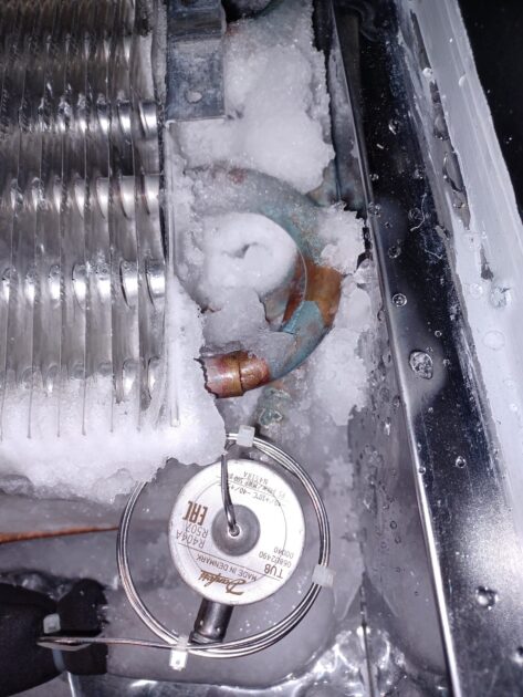
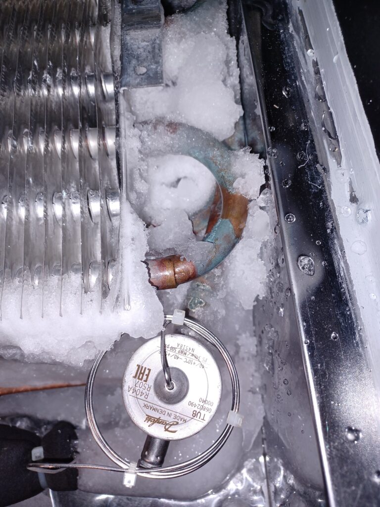
  • Ice forms on the pipes or directly on the evaporator.

  • An unusually low pressure is observed on either the low- or high-pressure side.

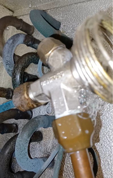
There are several ways to check for leaks. A simple visual method is to use soapy water (or special leak detection spray) to spray potential leak points. If the system is still pressurized, soap bubbles will form at the leak – as shown in the picture. In this case, the screw connection was the cause of the leak.

Another option is measurement . Larger systems often have pressure gauges – one on the low-pressure side (suction side) and one on the high-pressure side (pressure side). However, this type of fault diagnosis is difficult for a layperson to assess, but it can potentially be clarified by phone with a specialist.

A leak detector offers an additional option for locating leaks – however, this requires having such a device. With a threaded connection (flared fitting), the union nuts can often simply be tightened. If, on the other hand, there is a hole in the copper pipe (e.g., worn through by vibrations) or a leak at a soldered joint, the pipe must be replaced or the joint professionally resoldered.

In any case, a specialist company must be consulted, as the refrigerant must be professionally extracted and refilled.


Error No. 2: Contaminated capacitors

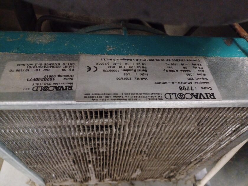
The condenser (also called the liquefier) ​​is the heat exchanger that releases heat during operation and therefore becomes warm (see image). The gaseous (superheated) refrigerant coming from the compressor flows into the condenser and undergoes three phases there: deheating , condensation , and subcooling .

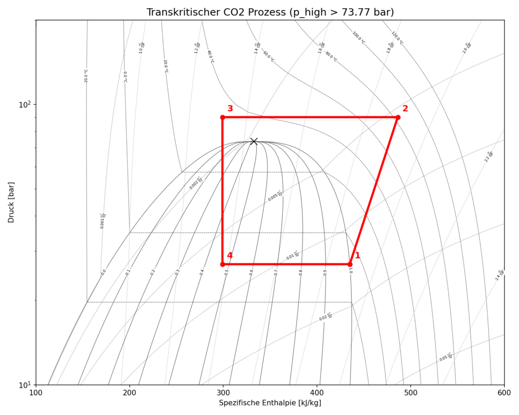
there are also refrigerants that operate in the transcritical range and are likely to become increasingly important in the future. A key example is R744 , better known as carbon dioxide ( This will not be discussed further here.

The condenser is a key component of the system, releasing heat from the refrigerant to the environment. If the condenser fins become clogged with dust, dirt, or leaves, heat can no longer be dissipated efficiently. Furthermore, the delicate fins on air-fed heat exchangers are often bent.

Both of these factors lead to increased pressure in the system and reduced cooling capacity – potentially resulting in complete system failure due to a high-pressure fault. These problems typically occur more frequently in summer due to high ambient temperatures.

What you can do: Clean the condenser fins regularly to ensure optimal performance. Be careful not to bend the fins. If they are already bent, you can carefully straighten them with a special fin comb.

Error No. 3: Icy evaporator

The evaporator is the component of a refrigeration system that absorbs heat from the surroundings. Inside the evaporator, the refrigerant evaporates – changing its state from liquid to vapor. This phase change allows a large amount of heat energy to be absorbed from the environment.

It is perfectly normal for frost to form very quickly on the evaporator surface, especially in the freezer compartment. This frost can rapidly grow into a thick layer of ice, which is why an automatic defrosting process is initiated at regular intervals.

However, if the defrost times are incorrectly set or the freezer is frequently opened (allowing warm, humid air – for example, during cooking – to enter), this significantly accelerates ice formation. In such cases, manual defrosting is often necessary, as the regular defrosting function is no longer sufficient.

Important: Be sure to switch the unit off completely before doing this! Defrosting with hot water works very well and speeds up the process. However, take meticulous care to protect the electronics from moisture and yourself from electric shock.

Error No. 4: Electrical problems

Refrigeration systems are complex and contain many electrical components. Common causes of electrical malfunctions include:

  • Poor connections or loose cables.

  • Blown fuses or defective contactors (relays).

  • Defective sensors (e.g. temperature sensors) and actuators.

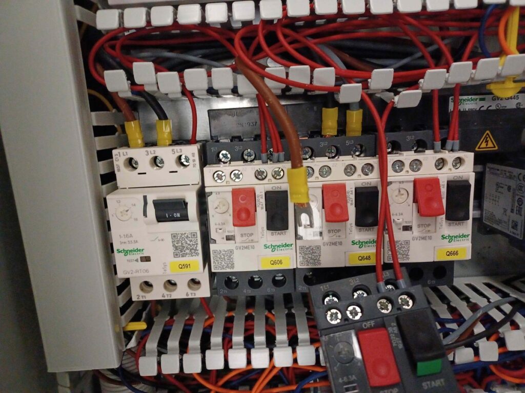
As part of proper maintenance, it is standard practice to tighten all electrical terminals to prevent loose connections. If a wiring diagram is available for the cooling system, the current path can be traced using a voltmeter. This usually allows for a very quick localization of where the current flow is interrupted.

Faulty fuses and relays must be replaced with new components. My recommendation here is very clear: Anyone without professional training in electrical work should absolutely leave it alone to protect themselves and others. Electricity is life-threatening!

If sensors are defective, this leads to incorrect control behavior of the system. The actual temperature values ​​can usually be read directly from the controller and should be compared with an external thermometer. Alternatively, sensors can be disconnected, their electrical resistance measured, and this compared with the characteristic curves in the manufacturer’s specifications. 

A faulty actuator, such as a solenoid valve, can often be identified by a distinct “click” when the coil is pulled on and off. Caution: If the coil is operated for too long without the metallic core (armature) while switched on, it will quickly overheat and be destroyed (due to the lack of inductive reactance). 

The fan motors on the evaporator or condenser also frequently fail and need to be replaced. 

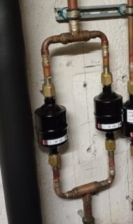
Error No. 5: Clogged filter dryers

The filter drier protects the system from contaminants and moisture. If it becomes clogged, the refrigerant flow is blocked, resulting in reduced cooling capacity and significantly higher energy consumption.

A blockage of the filter drier due to contamination is easily recognizable by the formation of frost immediately after the filter drier . A significant temperature difference between the filter inlet and outlet is also a sure sign of a blockage.

What you can do: A clogged filter dryer cannot be cleaned and must be replaced by a refrigeration technician. Ideally, this replacement should be carried out as a preventative measure during regular maintenance to avoid system malfunctions in the first place.

Summary and Conclusion

Many of the most common problems in refrigeration systems can be avoided through regular maintenance and early detection of symptoms . A clean system, free of leaks and dirt, not only operates more efficiently but also has a significantly longer lifespan.

Invest in professional maintenance to ensure the performance of your refrigeration system and avoid unexpected breakdowns.

Have you ever experienced any of these errors? Share your experiences in the comments!

Five common mistakes in refrigeration systems Read More »

Unkategorisiert
Measurement, control and automation technology


Programmable logic controllers are the heart of any automated system.

Eine speicherprogrammierbare Steuerung besteht aus einer CPU, die den programmierten Code abarbeitet bzw. Tasks ausführt. Es gibt unterschiedliche Möglichkeiten eine SPS zu programmieren, dies ist normiert in IEC 61131. Um die meiner Meinung nach wichtigsten aufzuzählen:

  • Strukturierter Text
  • FuP

Am flexibelsten kann man meiner Meinung nach mit strukturiertem Text programmieren.

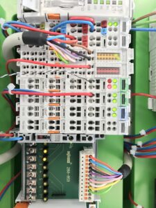
Steckkarten

Eine SPS lässt sich hardwareseitig meistens modular aufbauen. Unterschiedliche Steckkarten erlauben es individuell digitale/analoge Ausgänge bzw. Eingänge zu erweitern oder zu reduzieren. Digitale Eingänge werden häufig dafür verwendet Zustände zu überprüfen (0 oder 1). Dies kann zum Beispiel ein Überspannungs-Schutz sein. Ist dieser ausgelöst wird es von der SPS registriert und ein Alarm oder Ähnliches gemeldet. Analoge Eingänge sind häufig für Sensoren wie Temperaturfühler vorgesehen. Digitale Ausgänge können dafür verwendet werden einen Alarmzustand an ein anderes System zu senden, obwohl dies häufig auch (zum Beispiel an eine Leitzentrale) via Modbus (Kommunikationsverbindung) übermittelt wird.  Analoge Ausgänge werden verwendet um Aktuatoren zu steuern wie beispielsweise Ventile oder Frequenzumrichter.

Analoge vs digitale Signale

Um zu verstehen warum es analoge und digitale Eingänge/Ausgänge gibt, muss ein Verständnis dafür vorhanden sein, was der Unterschied zwischen diesen verschiedenen Signaltypen ist. Digitale Signale sind Signale, welche ein Computer verarbeiten kann. Hierbei handelt es sich um diskrete Werte, die durch das aneinander-reihen von Nullen und Einsen gebildet werden. Dabei ist grob-gesagt eine positive Spannung eine Eins und eine negative Spannung eine Null. Physikalische Signale wie Temperatur und Druck sind analoge Signale, die nicht abgehakt auftreten sondern als kontinuierliches Signal.

Beispiel: An einem Temperatur-Sensor wird eine Spannung angelegt. Im Sensor befindet sich ein PTC oder NTC Widerstand. Der Widerstand verändert sich proportional zu der jeweiligen Temperatur. Es kommt zu einem messbar-unterschiedlichem Spannungsabfall am Sensor.

Signalumwandlung

AD-Wandler oder DA-Wandler sind die Schnittstelle zwischen der analogen und der digitalen Domain. Bei einem analogen Eingangs-Signal wie das Beispiel mit dem Temperatur-Sensor, muss die Spannung umgewandelt werden, damit der Computer den Zahlenwert lesen kann. Da ein Computer nur diskrete Werte verarbeiten kann wird das Signal mit einer bestimmten Abtastfrequenz abgetastet.

Bei einem DA-Wandler verhält es sich genau umgekehrt. Ein digitales Signal, zum Beispiel eine Stellgröße für einen Frequenzumformer, muss in ein kontinuierliches analoges Signal umgewandelt werden, wie eine Spannung zwischen 0 und 10 V. Die Wandlung von diskreten zu kontinuierlichen Werten geschieht durch Glättungs-Filter.

Modbus
Modbus wurde 1979 entwickelt und ist heute aufgrund seiner Einfachheit und Lizenzfreiheit ein weltweiter Standard. Es basiert auf einer Client-Server- (früher Master-Slave-) Architektur, bei der ein Gerät Anfragen sendet und das andere antwortet.
  • Modbus RTU (Seriell): Überträgt Daten binär über RS-232 oder RS-485. Es ist robust, kostengünstig und ideal für einfache Feldgeräte über längere Distanzen.
  • Modbus TCP (Ethernet): Nutzt Standard-Ethernet-Kabel und das TCP/IP-Protokoll. Es ist deutlich schneller als RTU und ermöglicht die Einbindung in moderne IT-Infrastrukturen.
  • Datenstruktur: Modbus arbeitet primär mit Registern (16-Bit-Werte) und Coils(einzelne Bits/Schaltausgänge).

Neben Modbus gibt es spezialisierte Protokolle, die je nach Anforderung (Geschwindigkeit, Sicherheit, Komplexität) gewählt werden:

    • PROFINET / PROFIBUS: Die Standards im Siemens-Umfeld für Echtzeit-Kommunikation und schnelle E/A-Zyklen.
    • EtherCAT: Bekannt für extrem hohe Geschwindigkeiten, oft in der Antriebstechnik (Servomotoren) eingesetzt.
    • EtherNet/IP: Nutzt Standard-Ethernet-Hardware.
    • OPC UA: Es bietet im Gegensatz zu Modbus eine starke Verschlüsselung und semantische Datenmodelle (Daten haben Namen und Typen, nicht nur Adressen).
    • MQTT: Ein Protokoll für das Internet der Dinge (IoT), um Daten einfach in Cloud-Systeme zu übertragen.
Linear vs nichtlineare Regelung
Diese Unterscheidung bezieht sich darauf, wie ein System auf Eingangsänderungen reagiert.
  • Lineare Regelung: Das Systemverhalten folgt dem Superpositionsprinzip (doppelter Input führt zu doppeltem Output). In der Praxis werden Prozesse oft um einen Arbeitspunkt herum linearisiert, um bewährte Werkzeuge wie den PID-Regler(Proportional-Integral-Derivative) einzusetzen.
  • Nichtlineare Regelung: Reale physikalische Effekte wie Reibung, Sättigung oder quadratische Abhängigkeiten (z. B. Luftwiderstand) machen Systeme nichtlinear. Wenn eine einfache Linearisierung nicht ausreicht, kommen Verfahren wie Gain Scheduling(Umschalten zwischen verschiedenen Regler-Parametern) oder die Ljapunow-basierte Regelung zum Einsatz. 
Modellbasierte Regelung
Moderne Steuerungen nutzen mathematische Abbilder der physikalischen Welt, um „vorausschauend“ zu handeln.
  • Modellbasierte Regelung: Hierbei dient ein mathematisches Modell der Regelstrecke dazu, den Regler optimal auf die Strecke abzustimmen. Dies verbessert die Performance gegenüber rein empirisch eingestellten Reglern ma.
  • Modellprädiktive Regelung (MPC): Der Regler berechnet auf Basis eines Modells und unter Berücksichtigung von Grenzwerten (z. B. maximale Ventilstellung) die optimalen Stellgrößen für einen zukünftigen Zeitraum.
    • Vorteil: Er kann Verzögerungen (Totzeiten) einplanen und komplexe Abhängigkeiten zwischen mehreren Ein- und Ausgängen (MIMO) gleichzeitig optimieren.
    • Einsatz: Ursprünglich in der chemischen Industrie und in Raffinerien beheimatet, ist die modellprädiktive Regelung auf SPS heute auch in der schnellen Fertigungstechnik zu finden. 

Measurement, control and automation technology Read More »

Unkategorisiert

R744: The Refrigerant of the Future, Part 1

R744 is the technical designation for ( ) when used as a refrigerant. While also very efficient.


Advantages of R744
  • Climate-friendly: It has a GWP (Global Warming Potential) of 1. For comparison: Conventional refrigerants such as R404A often have a GWP value of almost 4,000.

  • Future-proof: As it is a natural substance, it is not subject to the strict restrictions or prohibitions of the F-Gas Regulation (applies to the EU).

  • Safety: R744 is non-flammable and non-toxic . It belongs to safety class A1. Nevertheless, a gas warning system must be installed due to the risk of asphyxiation, and possibly other measures as well.

  • High efficiency: R744 has a high volumetric cooling capacity. It is very well suited for indirect systems with flooded evaporators due to its low dynamic viscosity (lower pipe friction/low distribution losses). Many northern countries (Norway, Canada, etc.) use R744 in heat pump operation (efficient operation at low evaporation temperatures down to approximately -50°C).


The technical challenges

Despite the environmental benefits, the use of R744 is technically demanding:

  • High operating pressure: R744 operates at significantly higher pressures than conventional refrigerants. In the so-called “transcritical” phase, pressures exceeding 100 bar can occur. This necessitates special, very robust components and piping. High-pressure lines are made of thicker-walled steel (steel/copper alloy K65) or steel. 

  • Critical point: The critical point of is already at approximately 31°C the gas can no longer be liquefied by simple liquefaction, which makes system control more complex.

  • Risk of suffocation: Because odorless and heavier than air, it can accumulate in basements or low-lying machine rooms in the event of leaks. Therefore, gas sensors are in indoor areas.

R744 in the subcritical range

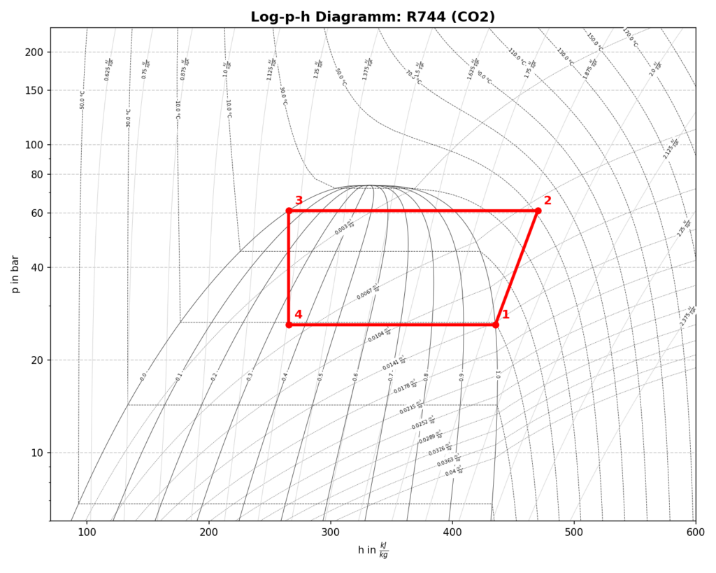
The right-hand log(p)-h diagram was created using the Python modules Fluprodia and Coolprop . It shows the left-hand cycle in the subcritical region. Superheating and subcooling were neglected. Compression is isentropic (frictionless), evaporation and condensation are isobaric, and expansion isenthalpic. 

R744 subkritisch

Just like with conventional refrigerants. From an energy perspective, subcritical operation is usually the goal (if fully possible due to the supercritical point).

R744 in the transcritical range

In summer, ambient temperatures easily reach over 30°C and the cooling system must be operated in the transcritical range.

R744 transkritisch
The specific values ​​for CO₂

Compared to conventional refrigerants (such as R134a, whose critical point is around 101 °C), the value for CO₂ is extremely low:

  • Critical temperature: approx. 31.1 °C

  • Critical pressure: approx. 73.8 bar


What is the supercritical point from a technical point of view?

The supercritical point marks the upper end of the vapor pressure curve. At this point, the densities of the liquid and gaseous phases equalize. This means:

  • No liquefaction: Above this point, CO₂ can no longer be liquefied by simply increasing the pressure.

  • State: The substance exists as a “supercritical fluid”—a state that combines properties of gases and liquids. And is therefore undefined.

The transcritical operating range in R744 refrigeration systems is more demanding from a control engineering perspective due to the fact that the pressure in the gas cooler (often between 80 and 100 bar) must be actively controlled (COP optimized). 

What optimization options are there to compensate for the poor efficiency in summer?

Over the past 20 years, extensive research has focused on increasing the efficiency of transcritical R744 refrigeration systems and making them more attractive and competitive in hot climates. Ejectors, expanders, and turbines are used to reduce the workload on the compressor. 

Problem description: 

The simplest way to operate a transcritical R744 system would be to expand the refrigerant directly to suction pressure after the gas cooler, as shown in the process diagram (see R744 transcritical ). The proportion of (poorly usable) vapor is very high in this scenario. Therefore, process optimization is recommended.

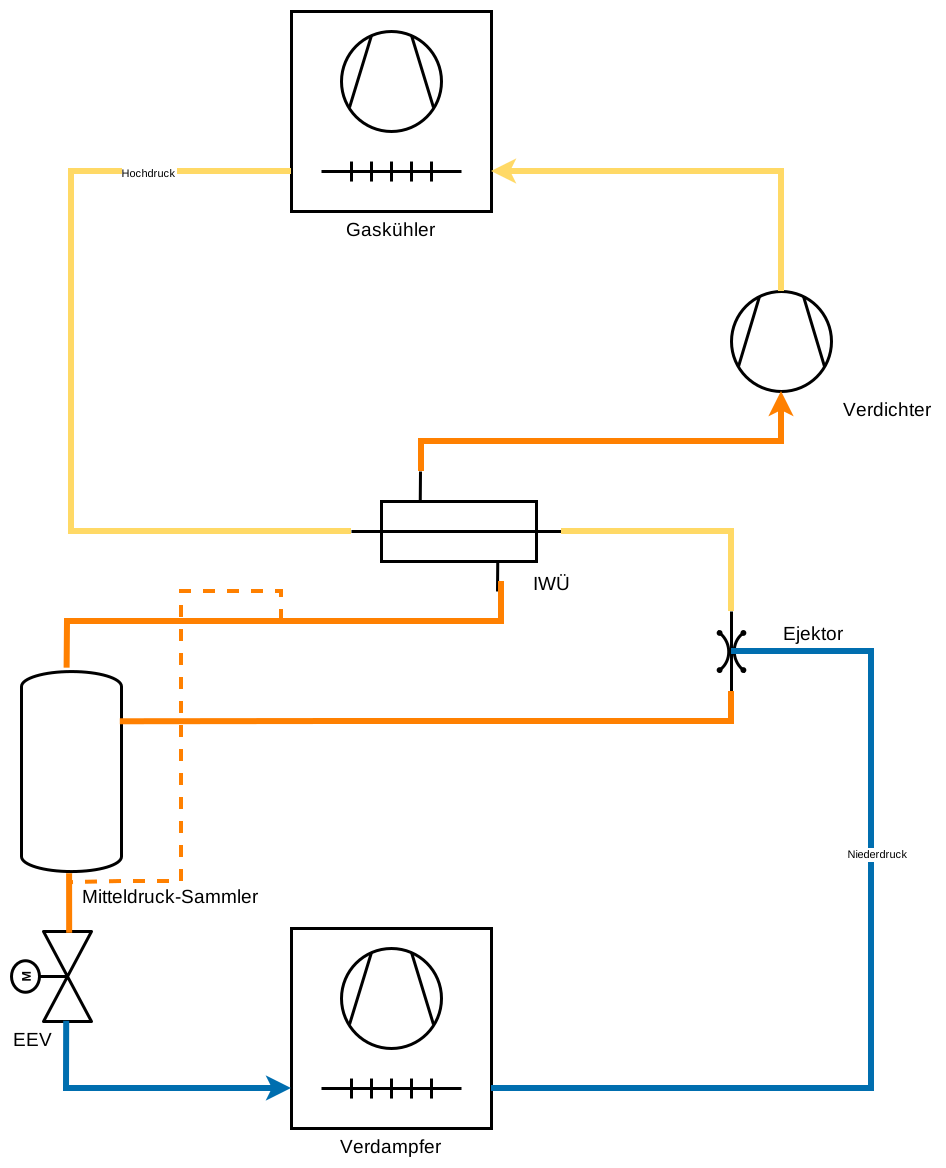
The solution: Flooded evaporator with internal heat exchanger and use of one or more ejectors

The image shows the operation of a flooded evaporator (i.e., without superheat control) and the use of an ejector. A further energy optimization is achieved through the integration of an internal heat exchanger.

In Anlehnung an [1] - Betrieb mit Ejektor
What exactly is an ejector?

The ejector operates according to the Bernoulli effect [1]. Refrigerant gas from the gas cooler enters the ejector via a nozzle. The refrigerant is accelerated significantly, and the static pressure drops sharply in this local area. Within this low-pressure space, the ejector is hydraulically connected to the evaporator (suction line). As a result of the local pressure drop, a suction effect occurs, and the refrigerant is drawn into the receiver. If you require further information, I would be happy to provide it. Just contact me!

The parallel compressor

The partially or completely evaporated refrigerant is not drawn directly into the compressor; instead, an ejector is used. The compressor then draws the vaporous portion directly from the receiver. As a result of this system optimization, less work is required from the compressor. 

Of course, there are many more optimization possibilities. One optimization widely used in supermarket refrigeration technology is multi-ejector operation [1]. If you are interested in this topic, let me know.

Sources
  1. “ECKERT, M. et al. (eds.). Natural refrigerants – applications and practical experience. In: Natural
    refrigerants – applications and practical experience. 1st edition. VDE Verlag, 2019.”
  2. Creation of the log(p)-h diagrams: “The Python script uses CoolProp (Copyright (c) Ian H. Bell et al.) and fluprodia (Copyright (c) Francesco Witte), licensed under the MIT license.”
Links

* Links marked with an asterisk are affiliate links. If you make a purchase through this link, I receive a small commission. The price remains the same for you.

Process diagram of a subcritical R744 plant. Includes a slider for displaying evaporation and condensing pressures. This tool is still under development. Preview by clicking the button below.

R744: The Refrigerant of the Future, Part 1 Read More »

Unkategorisiert
Scroll to Top