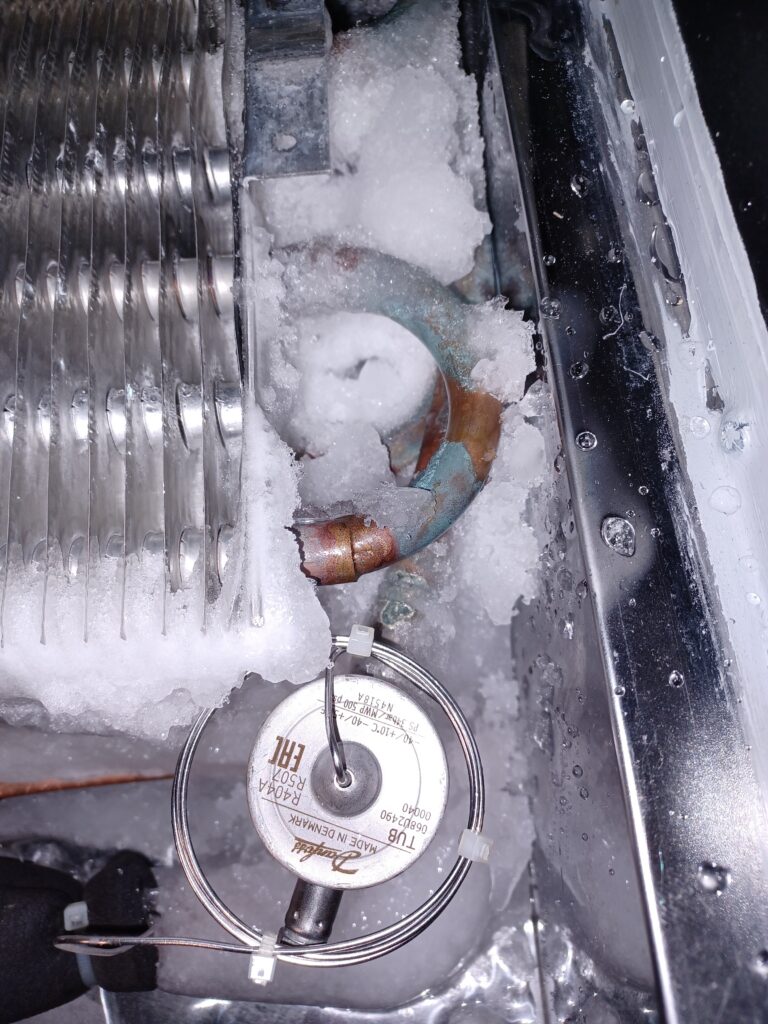
R744 is the technical designation for carbon dioxide ( CO₂ ) when used as a refrigerant. While CO₂ is considered a greenhouse gas in the atmosphere, it is one of the most environmentally friendly refrigerants (GWP of 1) and , depending on the application , also very efficient.
Advantages of R744
Climate-friendly: It has a GWP (Global Warming Potential) of 1. For comparison: Conventional refrigerants such as R404A often have a GWP value of almost 4,000.
Future-proof: As it is a natural substance, it is not subject to the strict restrictions or prohibitions of the F-Gas Regulation (applies to the EU).
Safety: R744 is non-flammable and non-toxic . It belongs to safety class A1. Nevertheless, a gas warning system must be installed due to the risk of asphyxiation, and possibly other measures as well.
High efficiency: R744 has a high volumetric cooling capacity. It is very well suited for indirect systems with flooded evaporators due to its low dynamic viscosity (lower pipe friction/low distribution losses). Many northern countries (Norway, Canada, etc.) use R744 in heat pump operation (efficient operation at low evaporation temperatures down to approximately -50°C).
The technical challenges
Despite the environmental benefits, the use of R744 is technically demanding:
High operating pressure: R744 operates at significantly higher pressures than conventional refrigerants. In the so-called “transcritical” phase, pressures exceeding 100 bar can occur. This necessitates special, very robust components and piping. High-pressure lines are made of thicker-walled steel (steel/copper alloy K65) or steel.
Critical point: The critical point of CO₂ is already at approximately 31°C . Above this temperature , the gas can no longer be liquefied by simple liquefaction, which makes system control more complex.
Risk of suffocation: Because CO₂ is odorless and heavier than air, it can accumulate in basements or low-lying machine rooms in the event of leaks. Therefore, gas sensors are mandatory in indoor areas.
R744 in the subcritical range
The right-hand log(p)-h diagram was created using the Python modules Fluprodia and Coolprop . It shows the left-hand cycle in the subcritical region. Superheating and subcooling were neglected. Compression is isentropic (frictionless), evaporation and condensation are isobaric, and expansion isenthalpic.
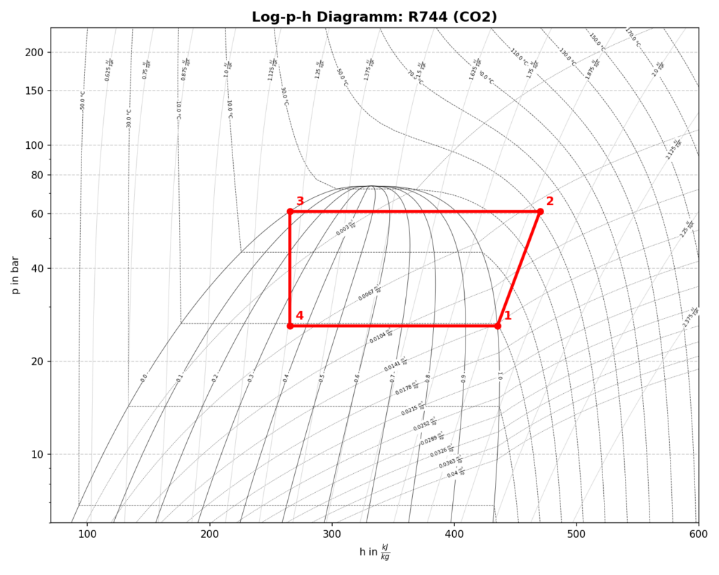
Just like with conventional refrigerants. From an energy perspective, subcritical operation is usually the goal (if fully possible due to the supercritical point).
R744 in the transcritical range
In summer, ambient temperatures easily reach over 30°C and the cooling system must be operated in the transcritical range.
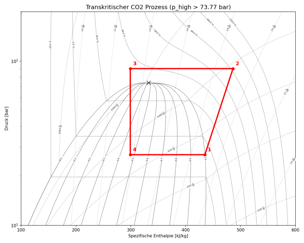
The specific values for CO₂
Compared to conventional refrigerants (such as R134a, whose critical point is around 101 °C), the value for CO₂ is extremely low:
Critical temperature: approx. 31.1 °C
Critical pressure: approx. 73.8 bar
What is the supercritical point from a technical point of view?
The supercritical point marks the upper end of the vapor pressure curve. At this point, the densities of the liquid and gaseous phases equalize. This means:
No liquefaction: Above this point, CO₂ can no longer be liquefied by simply increasing the pressure.
State: The substance exists as a “supercritical fluid”—a state that combines properties of gases and liquids. And is therefore undefined.
The transcritical operating range in R744 refrigeration systems is more demanding from a control engineering perspective due to the fact that the pressure in the gas cooler (often between 80 and 100 bar) must be actively controlled (COP optimized).
What optimization options are there to compensate for the poor efficiency in summer?
Over the past 20 years, extensive research has focused on increasing the efficiency of transcritical R744 refrigeration systems and making them more attractive and competitive in hot climates. Ejectors, expanders, and turbines are used to reduce the workload on the compressor.
Problem description:
The simplest way to operate a transcritical R744 system would be to expand the refrigerant directly to suction pressure after the gas cooler, as shown in the process diagram (see R744 transcritical ). The proportion of (poorly usable) vapor is very high in this scenario. Therefore, process optimization is recommended.
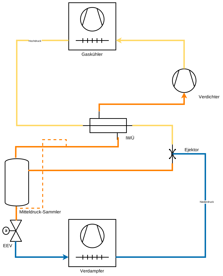
The solution: Flooded evaporator with internal heat exchanger and use of one or more ejectors
The image shows the operation of a flooded evaporator (i.e., without superheat control) and the use of an ejector. A further energy optimization is achieved through the integration of an internal heat exchanger.
What exactly is an ejector?
The ejector operates according to the Bernoulli effect [1]. Refrigerant gas from the gas cooler enters the ejector via a nozzle. The refrigerant is accelerated significantly, and the static pressure drops sharply in this local area. Within this low-pressure space, the ejector is hydraulically connected to the evaporator (suction line). As a result of the local pressure drop, a suction effect occurs, and the refrigerant is drawn into the receiver. If you require further information, I would be happy to provide it. Just contact me!
The parallel compressor
The partially or completely evaporated refrigerant is not drawn directly into the compressor; instead, an ejector is used. The compressor then draws the vaporous portion directly from the receiver. As a result of this system optimization, less work is required from the compressor.
Of course, there are many more optimization possibilities. One optimization widely used in supermarket refrigeration technology is multi-ejector operation [1]. If you are interested in this topic, let me know.
Sources
- “ECKERT, M. et al. (eds.). Natural refrigerants – applications and practical experience. In: Natural
refrigerants – applications and practical experience. 1st edition. VDE Verlag, 2019.” - Creation of the log(p)-h diagrams: “The Python script uses CoolProp (Copyright (c) Ian H. Bell et al.) and fluprodia (Copyright (c) Francesco Witte), licensed under the MIT license.”
Links
* Links marked with an asterisk are affiliate links. If you make a purchase through this link, I receive a small commission. The price remains the same for you.
Process diagram of a subcritical R744 plant. Includes a slider for displaying evaporation and condensing pressures. This tool is still under development. Preview by clicking the button below.